Elements, materials & sections
The beam element
EduBeam has one element type: a 2D Timoshenko beam in the x–z plane with three degrees of freedom at each end (Dx, Dz, Ry). It carries axial force, shear and bending, and includes shear deformation, which is why the cross section has a shear coefficient. The full formulation is in the theory manual.
Results along an element are exact for the linear model, so one element per member is enough. Add intermediate nodes only where you need a support, a hinge, a change of section, or a node to read results at.
Adding elements
| Method | How |
|---|---|
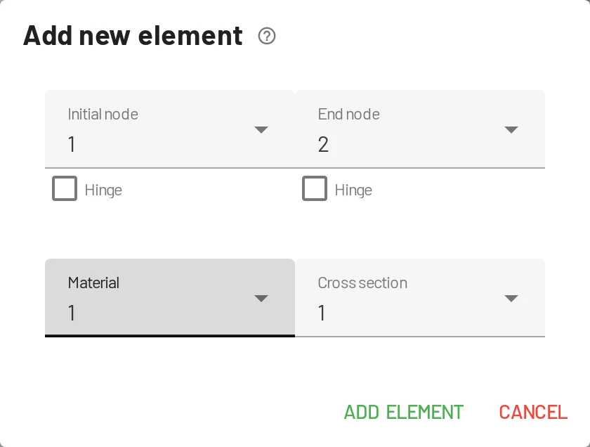
| Dialog | Elements tab → the first Add element button, or the canvas menu → Add element. Choose the Initial node and End node, the hinges, the material and the cross section. |
| Mouse | Elements tab → the second Add element button (cursor icon), or hold Ctrl with the canvas menu item. Click a node to start, then the next node to connect; clicking empty canvas creates a node there. Keep clicking to draw a polyline, and press Esc to finish. The banner at the top sets Start hinge and End hinge for every element you draw. The first material and cross section in the model are used. |
Materials and sections first
An element needs a material and a cross section. If there are none, the viewer shows No materials defined / No cross sections defined with an Add new button.
Element direction
The local x axis runs from the initial node to the end node. This matters for:
- loads in local coordinates (LCS ticked),
- the Load position from start node of concentrated loads,
- the order of end forces (
X12, Z12, M12at the start,X21, Z21, M21at the end) in the results table.
Use the swap button between the two nodes in the Elements table to reverse an element.
End hinges
Each element has two End hinges checkboxes, start and end, in the Elements table. They are also in the Add element dialog, in the element's Edit element panel, and in the banner when drawing with the mouse. A ticked hinge releases the bending moment at that end, so:
- one hinge makes a pin inside a frame or a continuous beam (the moment is zero there);
- both hinges make a truss bar that carries axial force only.
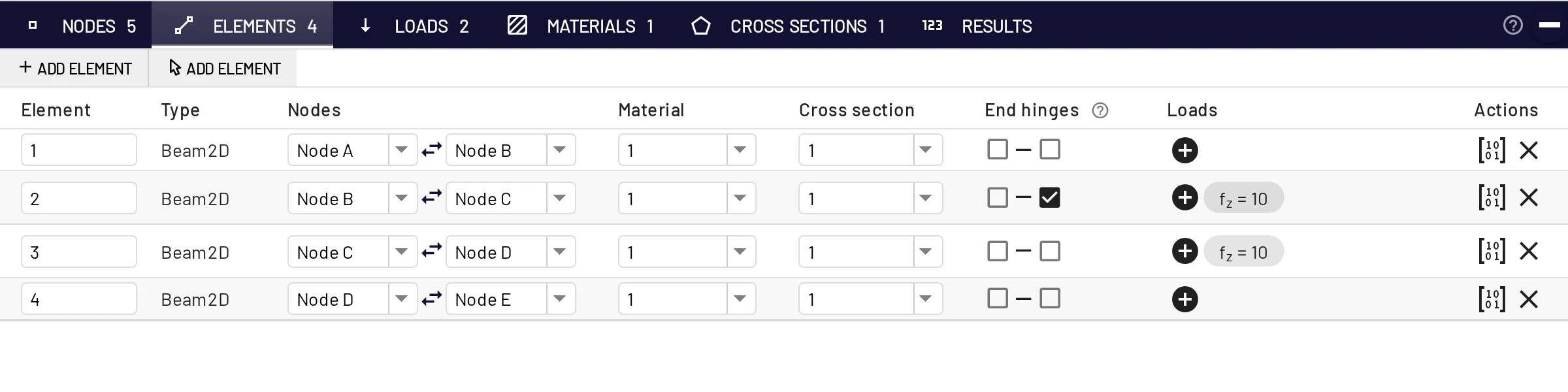
When two elements meet at a node and only one of them is hinged, the other still carries moment into the node. So hinge the element you want released, not "the node". If hinges make the structure a mechanism, EduBeam circles them and shows how it moves.
Editing and deleting
Click an element and use its panel (Edit element, Add load, Stiffness matrix, Delete), or edit it in the Elements table. Deleting an element also removes its loads. Stiffness matrix opens a window with the element's 6 × 6 stiffness matrix in global coordinates (N/m, N and N·m), with any end hinges already condensed. It is handy for checking hand assembly.
Materials
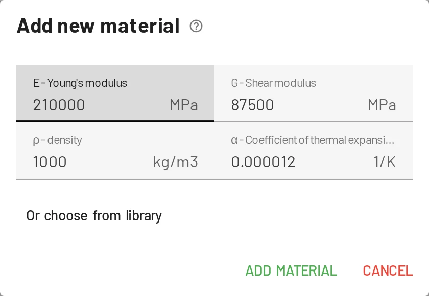
Materials tab → Add material:
| Field | Symbol | Unit | Notes |
|---|---|---|---|
| Young's modulus | pressure unit (MPa by default) | Steel ≈ 210 000 MPa, concrete ≈ 30 000 MPa, timber ≈ 11 000 MPa | |
| Shear modulus | pressure unit | ; steel ≈ 81 000 MPa. It only affects the Timoshenko shear term. | |
| Density | mass / length³ (kg/m³, lb/ft³) | Stored with the project. The static solver does not use it (there is no self-weight load). | |
| Coefficient of thermal expansion | 1/K or 1/°F | Used by temperature loads. Steel: 12 × 10⁻⁶ /K. |
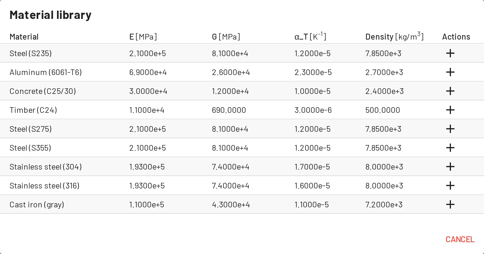
Material library has ready-made materials. The family that matches your units is listed first.
- Metals: structural steels S235, S275, S355, stainless steels, cast iron, aluminium alloys, copper, brass, bronze, titanium; US steels ASTM A992, A36, A572 Gr. 50 and HSS A500 Gr. C.
- Concrete: normal and lightweight concrete, classes C25/30, C30/37, C40/50, and f′c = 4 ksi and 5 ksi.
- Timber: C24, GL24h, GL32h.
- Other: glass, GFRP, CFRP, HDPE, PVC, PMMA, polycarbonate.
Open it with the toolbar button or Or choose from library in the Add material dialog.
A material that elements still use cannot be deleted; reassign those elements first.
Cross sections
Cross sections tab → Add cross section:
| Field | Symbol | Unit | Notes |
|---|---|---|---|
| Area | area unit | Axial stiffness | |
| Second moment of area | second-moment unit | Bending stiffness about the axis perpendicular to the drawing | |
| Height | section-dimension unit | Used by temperature-gradient loads (curvature ) | |
| Shear coefficient | – | Timoshenko shear correction factor: the effective shear area is . Use 1 to nearly ignore shear deformation, about 0.83 for rectangles, for I-sections. |
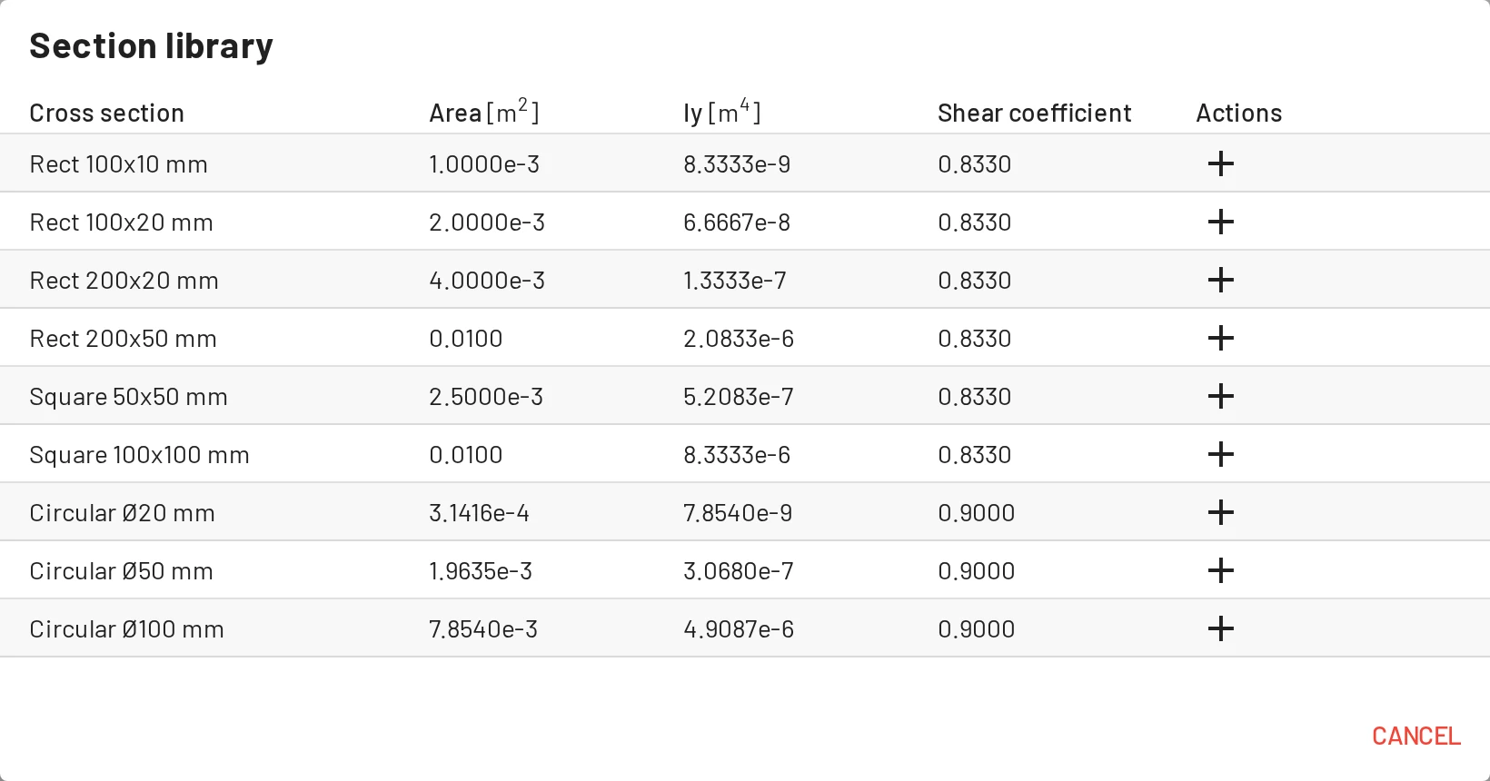
Section library gives approximate values for rectangles, squares and circles, IPE and HEA profiles, RHS and CHS tubes, and the AISC W-shapes and HSS (rectangular and round). Its shear coefficients follow the shape: for I-shapes, for rectangular tubes, 0.5 for round tubes, 0.833 for rectangles and 0.9 for circles. Treat the values as starting points and check them against a section table before relying on them.
Polygonal sections
Cross sections tab → Polygonal section, or Or define a polygonal shape in the Add cross section dialog, opens a shape editor.
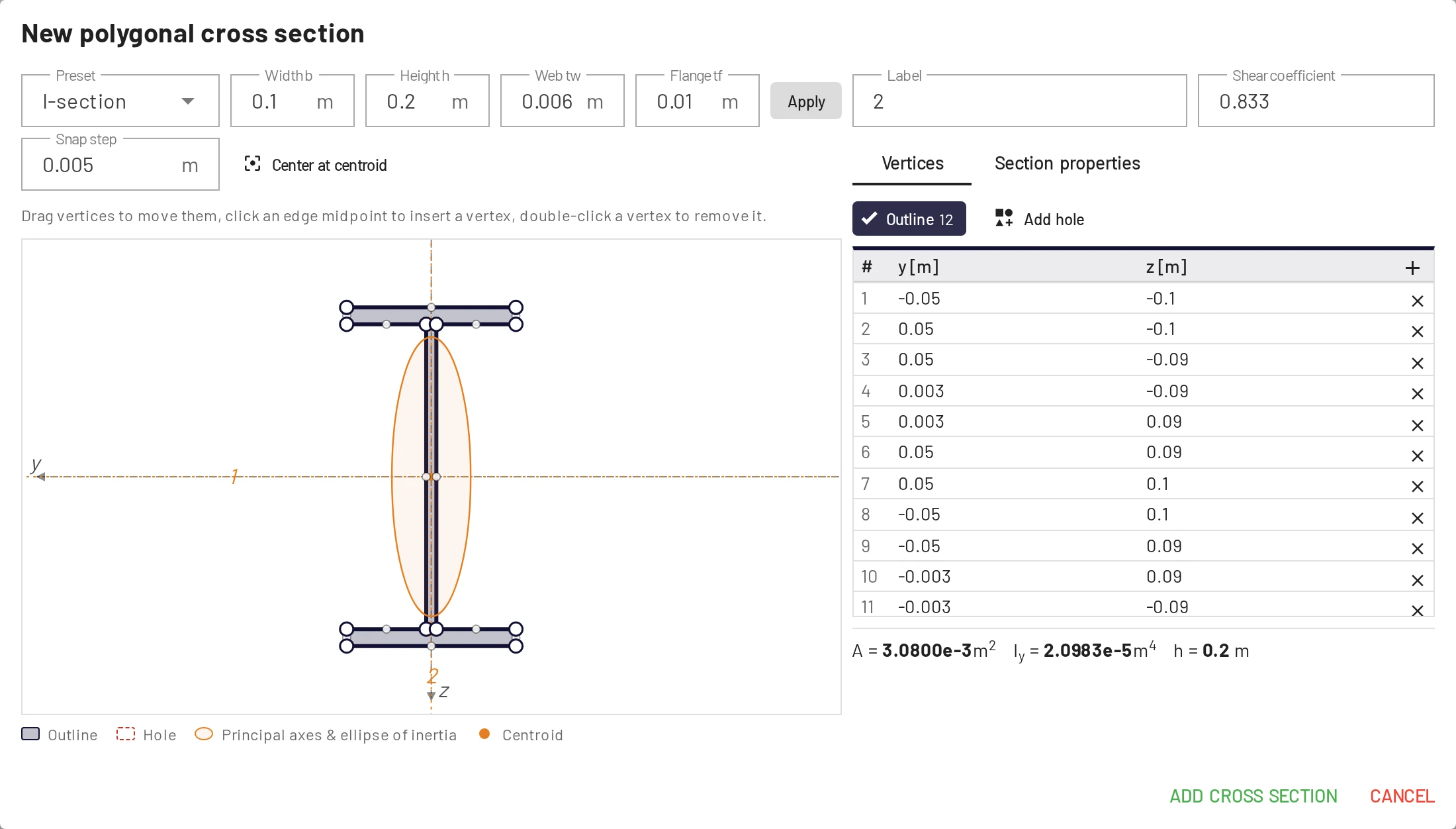
- Start from a preset (rectangle, I, T, L, channel, rectangular or circular hollow, circle) with its dimensions, then press Apply.
- Edit the shape: drag vertices (they snap to the Snap step), click an edge midpoint to insert a vertex, double-click a vertex to remove it, or type coordinates in the vertex table. Add hole adds an inner contour. Center at centroid moves the shape so its centroid is at the origin.
- Read the area , the centroid, the centroidal second moments , , , the principal moments , with the principal-axis angle (from to axis 1), and the radii of gyration. The drawing shows the ellipse of inertia.
On save, , and are filled in from the shape. They show as read-only in the table; use the polygon button in the Actions column to edit the shape again. The shear coefficient is still yours to enter. Section coordinates are local and right-handed, with pointing out of the screen, to the left and down.
If the shape is not symmetric about the plane of the frame (an L-angle, for example), the editor warns that a 2D analysis is exact only if the member is held against sideways deflection and twisting along its whole length, for example by a slab. When is significant, you choose which bending stiffness to use: held sideways and against twisting along its length () or free to deflect sideways, which is lower. Twisting is not included in either case.
Quick sanity values
For a rectangle : , . For a solid circle of diameter : , .
Materials and sections can be shared by any number of elements. Changing a value updates every element that uses it and solves the model again.