Tutorial: plane truss
This tutorial builds a small statically determinate truss, checks its bar forces with the method of joints and the method of sections, and finds a zero-force member. Allow about 15 minutes.
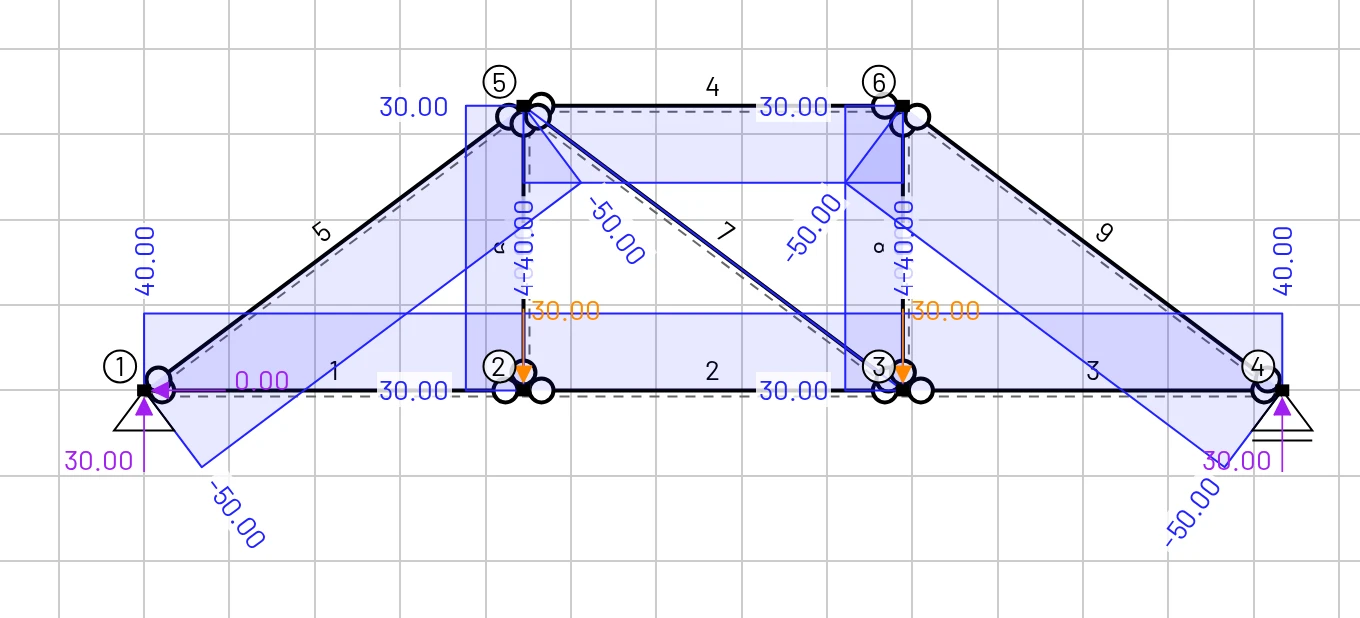
Open the finished model if you only want to explore it.
The problem
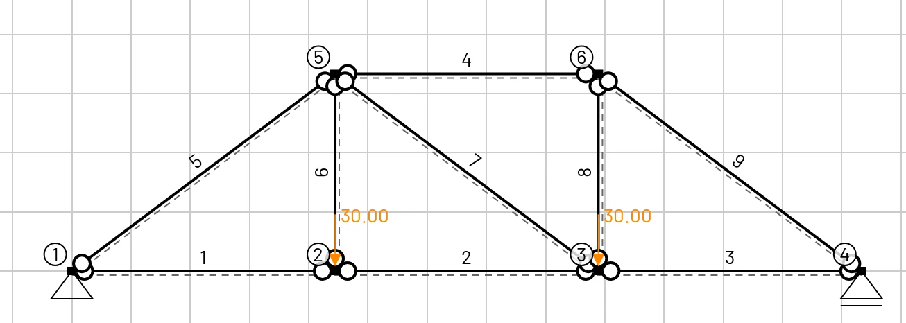
- A 12 m span in three 4 m panels, 3 m deep.
- Bottom chord nodes 1–4, top chord nodes 5 and 6.
- A pin at node 1 and a roller at node 4.
- Two loads of 30 kN, at the bottom-chord nodes 2 and 3.
- Steel bars with cm².
| Node | X [m] | Z [m] | Support | Load |
|---|---|---|---|---|
| 1 | 0 | 0 | pin | |
| 2 | 4 | 0 | Fz = 30 kN | |
| 3 | 8 | 0 | Fz = 30 kN | |
| 4 | 12 | 0 | roller | |
| 5 | 4 | −3 | ||
| 6 | 8 | −3 |
Bars: bottom chord 1–2, 2–3, 3–4; top chord 5–6; end diagonals 1–5 and 6–4; verticals 2–5 and 3–6; and the middle diagonal 5–3.
Is it determinate? with joints, so yes: the bar forces follow from equilibrium alone.
1. Material and section
- Clear mesh (tick Delete materials and Delete cross sections).
- Materials → Material library → Steel (S235).
- Cross sections → Add cross section:
Area = 0.002,Iy = 1e-6,Height = 0.1,Shear coefficient = 1. With hinged bars, only the area matters.
2. Draw the bars with hinges
A truss bar in EduBeam is a beam element with both end hinges ticked. The mouse tool can set them for you:
- Elements tab → the second Add element button (cursor icon).
- In the banner at the top of the viewer, tick Start hinge and End hinge. Every bar you draw now gets both.
- Draw the outline as one polyline: click (0, 0), (4, −3), (8, −3), (12, 0), then back along the bottom: (8, 0), (4, 0), (0, 0). Press Esc.
- Draw the inner bars one at a time, pressing Esc after each: (4, 0) → (4, −3), (4, −3) → (8, 0), (8, 0) → (8, −3).
- Press F to fit.
Check the Elements table: nine elements, each with both End hinges ticked. Your node and element numbers may differ from the pictures; that does not matter.
3. Supports and loads
- Click the node at (0, 0) → Node supports → pin. Click the node at (12, 0) → roller.
- Click the node at (4, 0) → Add load →
Fz = 30kN. Do the same at (8, 0).
Positive Fz points down. The joints of a truss are free to rotate; EduBeam accepts nodes where every bar is hinged and reports their rotation as 0.
4. Results
In the display options, untick Deformed shape and My (x) (there is no bending in a truss) and tick N (x).
5. Check by hand
Reactions. The loads are symmetric, so kN upward, and the horizontal reaction at the pin is zero.
Joint 1 (method of joints). The end diagonal 1–5 is 5 m long (, ):
Joint 2. The vertical 2–5 is the only bar that can carry the 30 kN load up: kN, and kN.
Section through the middle panel. Cut bars 5–6, 5–3 and 2–3 and keep the left part:
- Moments about node 3: kN.
- Vertical forces: the shear in the panel is , so the diagonal 5–3 carries nothing: .
| Bar | Hand value | EduBeam |
|---|---|---|
| Bottom chord 1–2, 2–3, 3–4 | +40 kN (tension) | 40 |
| Top chord 5–6 | −40 kN (compression) | −40 |
| End diagonals 1–5, 6–4 | −50 kN | −50 |
| Verticals 2–5, 3–6 | +30 kN | 30 |
| Middle diagonal 5–3 | 0 | 0 |
The deflection of node 2 is 2.29 mm (Results → Nodal results). Compute it with virtual work, , as an exercise.
6. Experiment
- Move one load. Put both 30 kN loads at node 2. The middle diagonal now carries force: which sign, and why?
- Remove the middle diagonal. The truss becomes a mechanism; EduBeam circles the hinges at fault and shows how the panel shears.
- Untick all the hinges. The truss becomes a frame with rigid joints. Tick My (x): the bending moments are tiny compared with the axial forces, which is why the pin-jointed idealisation works.
- Pin both supports. One more reaction makes it indeterminate, and the bottom chord forces now depend on the bar areas.