Nodes & supports
Nodes are the points of the model. Elements connect nodes, and supports and nodal loads are attached to nodes.
Coordinates
Every node has an X and a Z coordinate in the current length unit. The x axis points right and the z axis points down on screen, so a column rising from the ground runs from Z = 0 to Z = −3, not +3. The axis indicator in the corner of the grid shows the orientation. If you prefer a vertical axis pointing up, switch to y-up axes in Settings.
Adding nodes
| Method | How |
|---|---|
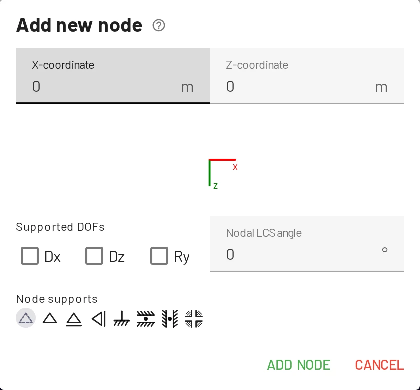
| Dialog | Nodes tab → the first Add node button, or right-click the canvas → Add node. Enter X and Z, and optionally the supports and the support angle. |
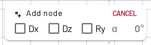
| Mouse | Nodes tab → the second Add node button (cursor icon), or hold Ctrl while choosing Add node in the canvas menu. Each click on the canvas adds a node. Press Esc or Cancel to stop. |
| While drawing elements | In mouse mode for elements, clicking empty canvas creates a node and connects it. |
| Copy & paste | Select nodes (and elements), press Ctrl+C and Ctrl+V, then click where the copy should go, or type an offset Δx, Δz and press Paste. |
Labels are assigned automatically (1, 2, … or continuing your own scheme, e.g. A, B) and can be renamed in the table.
Snapping
With Snap to grid on (S or the S chip), nodes you place or drag land on multiples of the Grid snap step: 0.1 m by default, or 0.5 ft in US units. Change it in Settings → Viewer settings → Grid. Turn snapping off for free placement, or type exact coordinates in the table afterwards.
Placing a node on an existing element
If you click close to an element while adding a node, EduBeam asks what you mean:
- Connect to structure splits the element in two (
1aand1b). Hinges at the outer ends are kept, and uniform and trapezoidal loads are divided between the halves; point and temperature loads go to the first half. This is the quickest way to add an interior support or a load point. - Place individual node creates the node on top of the element without connecting it.
Editing nodes
- Table: edit the label, X and Z in place.
- Drag: move a node in the viewer, on a touch screen too: press the node and drag. Every move can be undone.
- Edit node dialog: the pencil in the table's Actions column. It holds the coordinates, supports and support angle, with a preview of the support symbol.
- Delete: the × in the table, Delete in the node's panel, or select it and press Delete. Deleting a node also deletes the elements and loads attached to it.
Supports
A support is a set of restrained degrees of freedom (DOFs). Each node has three:
| DOF | Meaning |
|---|---|
| Dx | translation along x (horizontal) |
| Dz | translation along z (vertical) |
| Ry | rotation about y (in the plane of the drawing) |
The quickest way is to pick the symbol. It is in the node's panel under Node supports, in the Add and Edit node dialogs, and as a small menu at the start of the Supported DOFs column of the Nodes table. Ticking the Dx, Dz, Ry boxes does the same thing one DOF at a time.
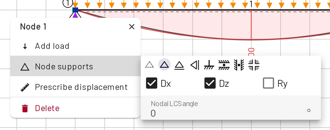
| Support | Restrained | Moves | Reactions |
|---|---|---|---|
| Free | none | everything | none |
| Pin | Dx + Dz | rotates | Rx, Rz |
| Roller | Dz | slides horizontally, rotates | Rz |
| Vertical roller | Dx | slides vertically, rotates | Rx |
| Fixed | Dx + Dz + Ry | nothing | Rx, Rz, M |
| Slider | Dz + Ry | slides horizontally | Rz, M |
| Vertical slider | Dx + Ry | slides vertically | Rx, M |
| Rotation only | Ry | slides both ways | M |
A reaction is computed, and drawn, for every restrained DOF.
Truss joints
Truss members are beam elements with both end hinges released (see Elements). A pin (Dx + Dz) at a truss support is the usual choice. A node where every connected element is hinged has no rotational stiffness; EduBeam accepts it and reports its rotation as 0.
Inclined (skewed) supports
Set the Nodal LCS angle α in degrees (−180…180). It is in the node's panel under Node supports, in the Add and Edit node dialogs, and in the α field of the Nodes table. The node's axes rotate by that angle and the support DOFs act in the rotated directions, so a roller on a 30° slope is Dz with α = 30. The symbol rotates accordingly and the reaction is reported in the rotated direction.
Stability
The solver needs at least three restrained DOFs in total, and the supports and hinges must hold the structure. Until there are enough supports the viewer shows a blue Needs supports chip. If the supports are enough in number but cannot hold the structure (all parallel, or meeting in one point), or hinges let members turn against each other, a red message names the problem and a dashed outline shows how the structure moves. See Troubleshooting.
Nodal loads and settlements
Forces, moments and prescribed displacements (support settlements) are applied at nodes. See Loads.
Dimension lines
Right-click the canvas → Add dimension to draw a dimension line between two points, or right-click an element → Dimension element to dimension it directly. End points snap to nodes when dragged close to them. Select a line and use Edit to type its coordinates, or Flip dimension to put the label on the other side. Dimension lines are cosmetic; they are saved with the project and travel in share links.