Loads
Loads act on nodes or along elements. All of them belong to a single load case and act together; to compare scenarios, save each one as a project file or share link.
| Load | Acts on | Add it from |
|---|---|---|
| Force or moment | a node | Loads tab → Add nodal load, or click the node → Add load |
| Prescribed displacement (settlement) | a supported node | the same dialog, or click the node → Prescribe displacement |
| Uniformly distributed, trapezoidal, concentrated or temperature load | an element | Loads tab → Add element load, or click the element → Add load |
Sign convention
x points right, z points down, and moments are positive counter-clockwise. So a positive Fz or fz is a downward, gravity-like load, and an upward load is negative.
| Positive | Default axes (z down) | y-up axes |
|---|---|---|
Horizontal force Fx, fx | to the right | to the right |
| Vertical force | Fz, fz: down | Fy, fy: up |
| Moment | My: counter-clockwise | Mz: counter-clockwise |
| Vertical settlement | Dz: down | Dy: up |
Loads in an element's local axes (LCS ticked) follow the element instead: local x runs from its initial node to its end node, and local z is local x turned 90° clockwise, towards the dashed line drawn along the element. See Element direction. The full convention, including internal forces, is in Coordinate system & sign conventions.
Nodal loads
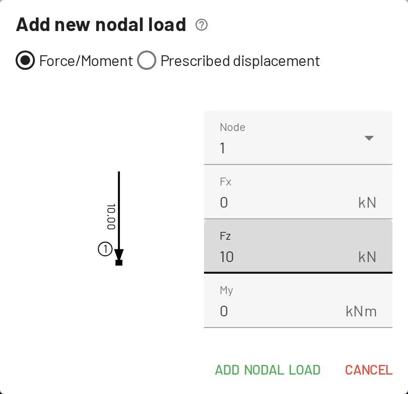
Loads tab → Add nodal load, or click a node → Add load, and keep Force/Moment selected. Enter the forces Fx, Fz (kN) and the moment My (kNm), with the signs above; the preview draws the load as you type.
- The components are in global axes. On a node with turned axes (an inclined support) the dialog adds a Global axes / Node axes switch. In node axes the components, shown as
Fx′andFz′, act along the node's own axes and turn with them if the angle changes later. Switching rewrites the numbers so the load stays where it is. - A node can carry several nodal loads; they add up.
Prescribed displacements (support settlements)
To move a support by a given amount, choose Prescribed displacement in the same dialog, or click a supported node → Prescribe displacement. Enter the displacements Dx, Dz (positive right and down, in the displacement unit, m by default) and the rotation Ry (rad, positive counter-clockwise).
- Only restrained DOFs can be prescribed: the other fields are greyed out, and a node with no support cannot have a settlement at all.
- A node has at most one prescribed displacement. To change it, edit it rather than adding a second.
- On an inclined support, the fields read
Dx′andDz′: the settlement acts along the support's own axes.
Whether a settlement causes internal forces depends on the structure. The same 10 mm settlement of support B, with no other load:
A statically determinate structure follows the support without resistance. The continuous beam has to bend: support B pulls it down by , like a point load at the middle of a simply supported 10 m span. With and the example steel's , that load is , the reaction at B, and . The continuous beam tutorial combines a settlement with loads.
Element loads
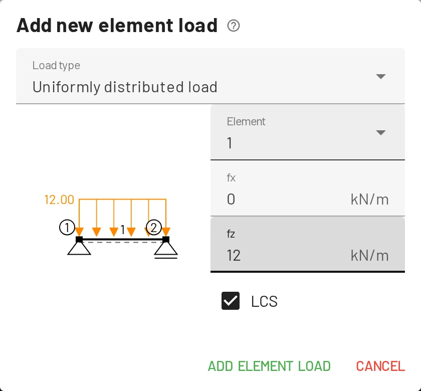
Loads tab → Add element load, or click an element → Add load. Choose the Load type; the preview shows the load on the element as you type. Forces are in kN and line loads in kN/m, or whatever units you have chosen.
Uniformly distributed load
A constant load per unit length, fx and fz, over the whole element. With LCS ticked (the default) they act along the element's local axes; unticked, along the global axes. On a horizontal element drawn left to right the two are the same; on an inclined member they are not:
| You want | Enter |
|---|---|
| a load perpendicular to the member (wind on a rafter) | fz with LCS ticked |
| a vertical load per metre of member (self-weight) | fz with LCS unticked |
| a vertical load per metre of horizontal projection (snow) | not available directly: multiply by , the member's slope, and enter it as a vertical load |
The same 10 kN/m on a rafter 4 m across and 3 m up, 5 m long:
By hand: perpendicular, ; vertical, the 50 kN spread over 4 m of span is 12.5 kN/m of projection, so .
Trapezoidal load
A load that varies linearly along the element: f1x, f1z at the initial node, f2x, f2z at the end node. Set one end to zero for a triangular load.
By hand: the total load acts at , so and ; the shear is zero, and the moment largest, at , where .
Trapezoidal loads act along the element's local axes (the LCS box is locked). On a horizontal element drawn left to right, that is the same as global; on an inclined one, f1z and f2z are perpendicular to the member and f1x, f2x along it.
A varying vertical load on a member at slope is still exact: enter its two local components at each end, and pointing down the slope, which is negative when the element runs uphill from its initial node. For the rafter above, 4 m across and 3 m up and drawn from the bottom, a vertical load growing from 0 to 10 kN/m of member is f1x = f1z = 0, f2x = −6 and f2z = 8 kN/m.
By hand: the 25 kN resultant acts two thirds of the way across, at 2.67 m, so . Over the 4 m projection the load is a triangle rising to 12.5 kN/m, so, as above, .
Concentrated load
A point force Fx, Fz or a moment My anywhere along an element, without an extra node. Load position from start node is its distance from the initial node, . It starts at half the length rounded down to whole metres, and at most 5 m (whole feet and at most 15 ft in US units), so set it to where your load is. LCS works as for uniform loads.
The shear diagram jumps by Fz at the load and the moment diagram has a kink there: , . A concentrated My makes the moment diagram jump instead.
Temperature load
| Field | Meaning | Effect |
|---|---|---|
| ΔTc, axial temperature change | the same change over the whole section | elongation |
| ΔTb − ΔTt | change of the bottom fibres minus the top fibres | curvature |
Both are temperature changes from the stress-free state, in °C by default; a change of 1 °C is 1 K. Temperature loads use the material's α and the section's height h. The bottom fibres are on the side of the dashed line. A positive ΔTb − ΔTt (warmer at the bottom) lengthens the bottom fibres, so the element sags like a beam under gravity load.
In a statically determinate structure, temperature only causes displacements. Restraint (fixed ends, continuity, redundant members) turns it into internal forces. The same 6 m steel beam, 0.3 m deep, 20 K warmer at the bottom than at the top:
By hand: the free curvature is . Simply supported, the beam takes it freely and sags . With fixed ends, a constant moment must undo it: . Checking results by hand works through another case.
Editing and removing loads
| To | Do this |
|---|---|
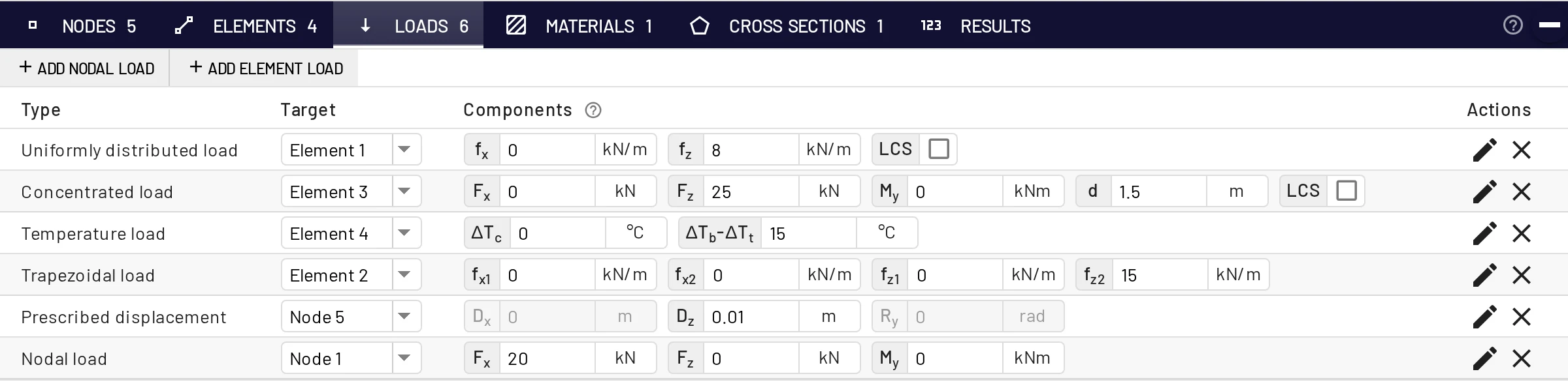
| Change values quickly | Edit the components (and the LCS box) in place in the Loads tab. |
| Open the edit dialog | Double-click the load in the viewer, or click it → Edit load. The loads also appear as chips in the Nodes and Elements tables; click one to edit it. |
| Delete it | Select it and press Delete, click it → Delete, or use the × in the Loads tab. |
Loads belong to their node or element: deleting the node or element deletes them, and copying it with its loads selected copies them.
What is not available
- One load case. No combinations: save each case as its own file or link.
- No self-weight. Add it as a uniform load, LCS unticked: , e.g. for an IPE 200.
- Trapezoidal loads in local axes only. For a varying vertical load on a sloped member, enter its local components.
- No partial line loads. A line load covers the whole element: add a node where it starts or ends.