Tutorial: three-hinged frame
A three-hinged frame is statically determinate: three equilibrium equations plus the condition at the hinge give all four support reactions. That makes it a perfect model for checking every number EduBeam draws. Allow about 15 minutes.
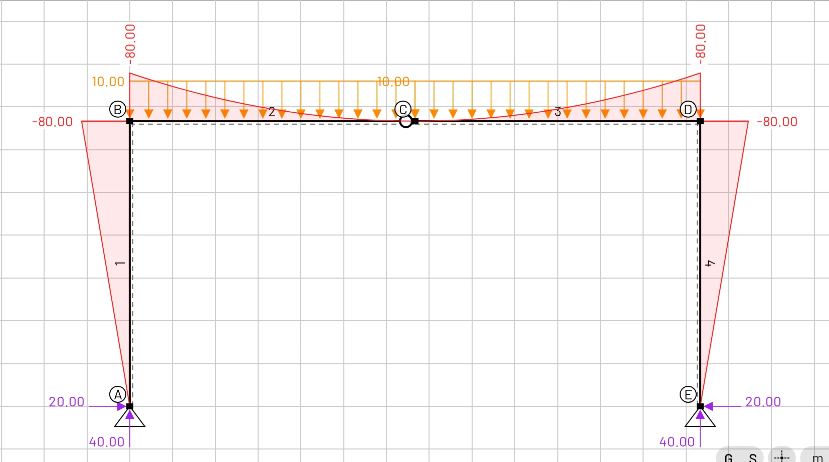
Open the finished model if you only want to explore it.
The problem
- Two 4 m columns, pinned at their bases A and E, 8 m apart.
- A horizontal beam B–D on top, with a hinge at mid-span C.
- A uniform load of kN/m on the whole beam.
- Steel ( GPa, GPa), IPE 300 ( cm², cm⁴, mm).
| Node | X [m] | Z [m] | Support |
|---|---|---|---|
| A | 0 | 0 | pin |
| B | 0 | −4 | |
| C | 4 | −4 | (hinge in the beam) |
| D | 8 | −4 | |
| E | 8 | 0 | pin |
Remember that z points down, so the top of the columns is at Z = −4.
1. Material and section
- Clear mesh (tick Delete materials and Delete cross sections).
- Materials → Material library → Steel (S235).
- Cross sections → Add cross section:
Area = 0.00538,Iy = 8.356e-5,Height = 0.3,Shear coefficient = 1.
The section only affects the displacements. This frame is determinate, so its internal forces do not depend on , or at all.
2. Draw the frame
The fastest way is one polyline with the mouse:
- Make sure Snap to grid is on (the S chip).
- Elements tab → the second Add element button (cursor icon).
- Click at (0, 0), then (0, −4), (4, −4), (8, −4) and (8, 0). Watch the rulers and the crosshair to find the points. Each click adds a node and connects it to the previous one.
- Press Esc to finish, then F to fit the frame to the screen.
You now have five nodes and four elements. The pictures here label the nodes A–E; rename yours in the Nodes table if you like, or keep 1–5. Check the coordinates in the table and fix any that missed the grid.
3. Supports and the hinge
- Click node A, open Node supports and pick the pin. Do the same for node E.
- In the Elements table, find the element from B to C and tick its end hinge (the second box in End hinges).
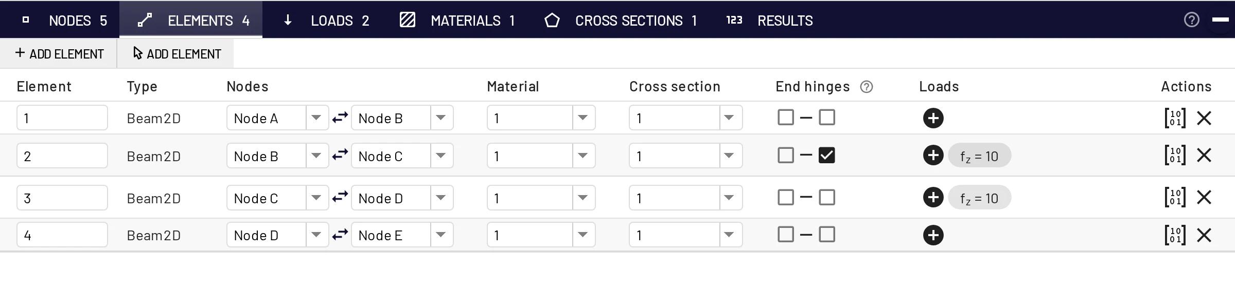
One hinge, not two
Hinging the end of element B–C is enough: the moment at C is then zero, because C–D cannot carry a moment into a node that only it holds rigidly. Tick the start of C–D as well and nothing changes. But tick a hinge at B too, and the frame becomes a mechanism. Try it: EduBeam shows you how it moves.
4. Load
Loads → Add element load → Uniformly distributed load, element B–C, fz = 10 kN/m. Repeat for element C–D. The beam is horizontal, so the LCS box makes no difference here.
5. Results
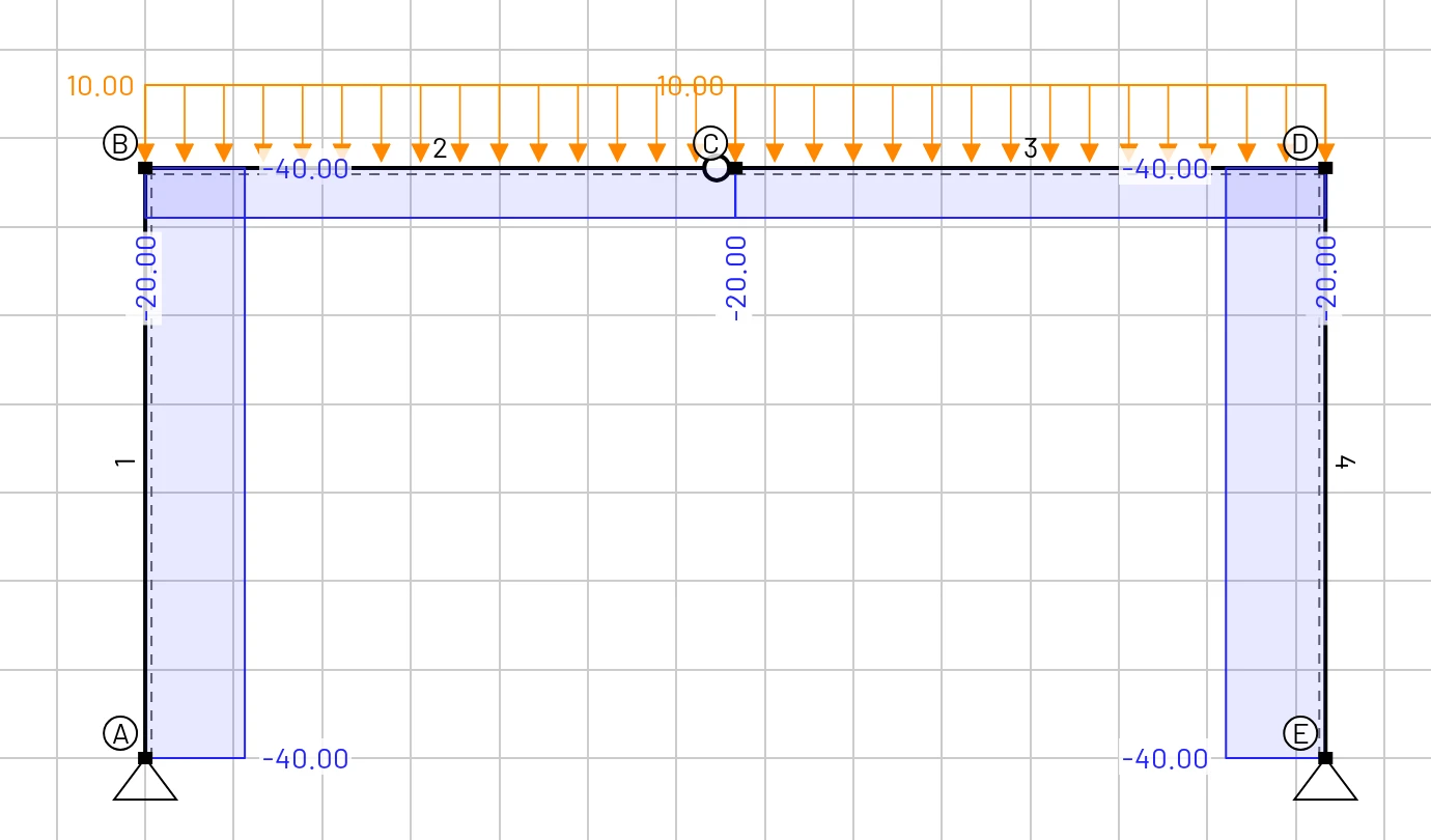
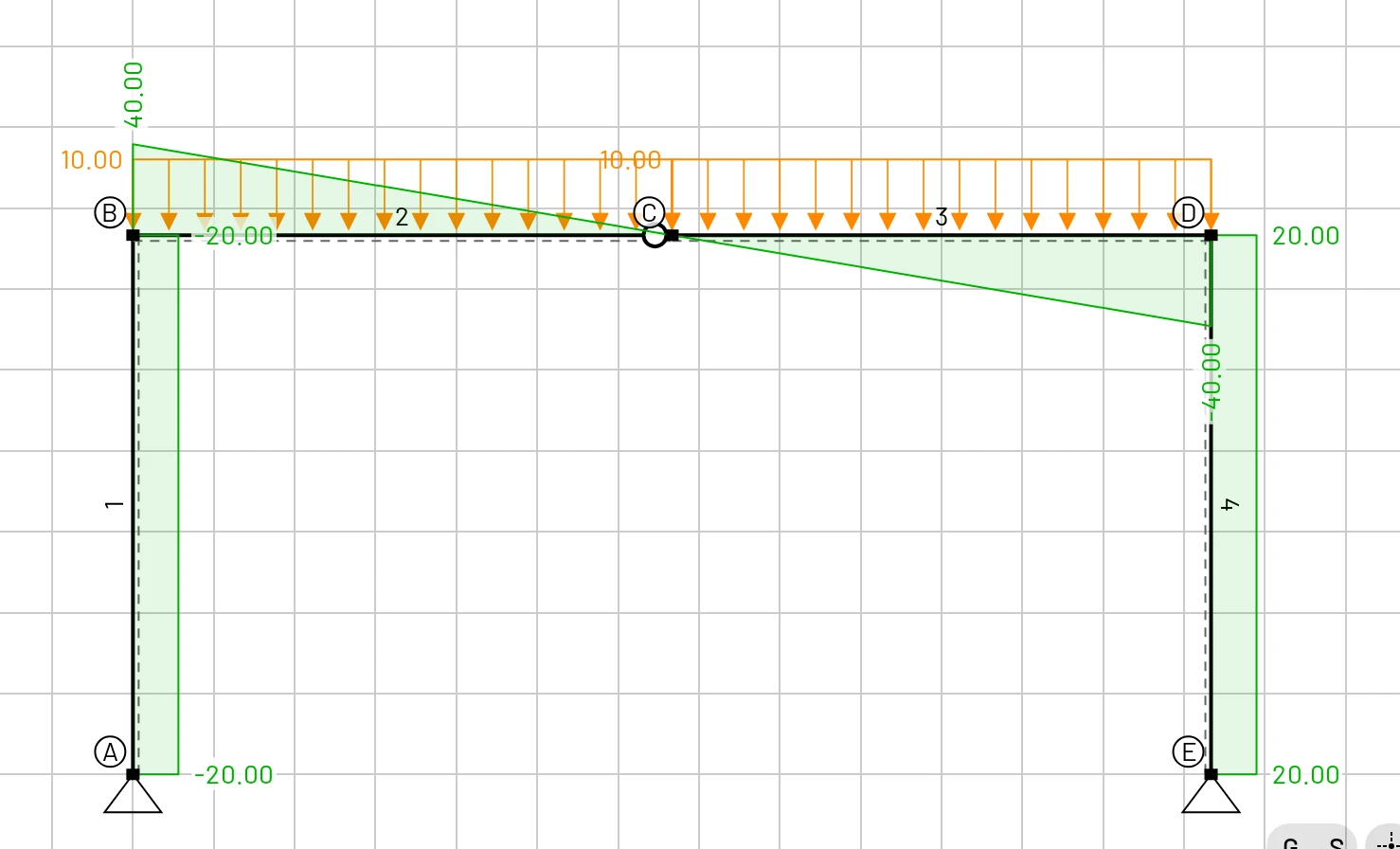
The display options start with the deformed shape, bending moment and reactions on. Tick N (x) and Vz (x) to see the rest.
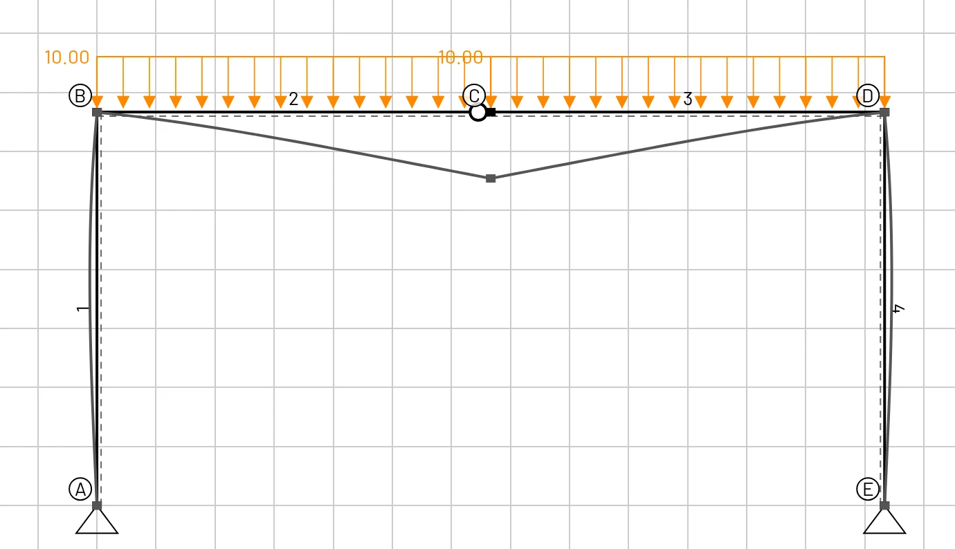
6. Check by hand
Vertical reactions. By symmetry, each base takes half the load:
Horizontal reactions. Take moments about the hinge C for the left half of the frame. The moment there must be zero:
Both bases push inward by 20 kN; that horizontal thrust is what makes a three-hinged frame efficient.
Internal forces.
| Quantity | Formula | Hand value | EduBeam |
|---|---|---|---|
| Vertical reactions | 40 kN | 40 kN | |
| Horizontal reactions | from | 20 kN | 20 kN |
| Moment at the corners B and D | 80 kNm, tension outside | −80 kNm | |
| Moment at the hinge C | 0 | 0 | |
| Normal force in the columns | −40 kN | −40 kN | |
| Normal force in the beam | −20 kN | −20 kN | |
| Shear in the columns | 20 kN | −20 kN (A–B), +20 kN (D–E) | |
| Shear in the beam at B | 40 kN | 40 kN | |
| Shear in the beam at C | 0 | 0 | |
| Shear in the beam at D | −40 kN | −40 kN |
The two columns have opposite shear signs although they carry the same force, because each element's local axes follow its direction: A–B is drawn upward and D–E downward. Swap the nodes of one column and its sign flips.
In the beam, kNm (x from B), which is zero at the hinge and never positive: the whole beam hogs. The shear falls to zero exactly at C, so the moment's extreme is at the hinge too.
Displacement. The hinge C sinks by 43.1 mm (Results → Nodal results, Dz of C). That comes from the bending of all four members and is a good exercise for the principle of virtual work.
7. Experiment
- Untick the hinge at C. The frame becomes once indeterminate; the corner moments drop and a sagging moment appears at mid-span. Now the section does matter: try a stiffer beam.
- Fix the bases (pick the fixed support). Moments appear at A and E.
- Add a horizontal load: a nodal load
Fx = 10kN at B. The frame sways, and the reactions are no longer symmetric. Check them with the same three equations and . - Tick a hinge at B as well. The frame is now a mechanism, and EduBeam animates how it can move.