Tutorial: inclined beam
Model a roof rafter under snow, read the normal and shear forces along its slope, and check them by hand.
- Time: about 15 minutes. This is the first and shortest of the four tutorials.
- You need: EduBeam open in a second tab, on a computer with a mouse and keyboard. Do the Quick start first if you have not used EduBeam before: it shows the tabs and dialogs this tutorial uses.
- Background: equilibrium of a simply supported beam, and splitting a force into two components.
- Units: SI. The units chip at the bottom right of the viewer should read
m m² kN kNm MPa. If it shows feet and kips, click it and set Unit system to SI (metric).
You will learn to
- turn a load given per metre of plan into the load along the member that EduBeam takes,
- point a line load vertically or perpendicular to the member with the LCS box,
- turn a roller, and see that it moves the normal force but not the bending moment.
The problem
- A straight rafter from node 1 at (0, 0) up to node 2 at (4, −3): 4 m in plan and 3 m high, so it is m long, with and .
- A pin at node 1, the eaves. At node 2, the ridge, a roller that rolls horizontally, so its reaction is vertical.
- Snow kN/m, given, as codes give it, per metre of plan (of horizontal projection).
- Steel, GPa, and m⁴, that of an IPE 300.
Is it determinate? Three reactions and three equations of equilibrium: yes. Its forces follow from statics alone; and only matter for the deflection.
Model it
Material and section
- Click Clear mesh in the app bar, tick Delete materials and Delete cross sections, and click Confirm. Nodes and elements are numbered from 1 again.
- Materials tab → Material library → + on the Steel (S235) row, then Cancel to close the library.
- Cross sections tab → Add cross section. Type
8.356e-5in Iy, keep Area, Height and Shear coefficient at1, and click Add cross section.
An area of 1 m² keeps the member from shortening or shearing noticeably, as the hand calculation assumes.
Draw the member
- Elements tab → the second Add element button, the one with the cursor icon.
- Click at (0, 0), then at (4, −3). The rulers and the crosshair show where you are, and the clicks snap to the grid.
- Press Esc to stop drawing, then F to fit the view.
The z axis points down, so node 2, 3 m above node 1, is at . Check both nodes in the Nodes table and type over any coordinate that missed.
Supports
Click node 1 → Node supports → the Pin symbol. Give node 2 the Roller the same way.
Load
The snow on the rafter is kN in all. EduBeam spreads a uniform load along the member's length, so the same 12 kN over 5 m is
- Loads tab → Add element load.
- Load type Uniformly distributed load, Element
1,fz = 2.4. - Untick LCS, so that
fzacts vertically, and click Add element load.
Results
The beam is solved as soon as the load is in. In the display options at the top right of the viewer (the cog shows and hides them), Deformed shape, My (x) and Reactions are on from the start; tick N (x) and Vz (x) as well. The switch under the figure at the top shows the same diagrams.
EduBeam labels diagrams and reactions in kN and kNm with two decimals, so you should read:
6.00at each support, upward. The pin's horizontal reaction reads0.00: no horizontal force acts.6.00kNm, the peak of the bending moment, at mid-span.4.80kN of shear at node 1 and-4.80at node 2.-3.60kN of normal force at node 1 (compression) and3.60at node 2 (tension), through zero at mid-span.
Check by hand
Reactions. The 12 kN resultant acts 2 m in plan from node 1, so moments about either end give kN. No horizontal force acts, so .
Bending moment. For vertical forces only the horizontal lever arms count. At a distance in plan from node 1,
exactly as for a horizontal beam of span m under the same load per metre of plan.
Shear and normal force. The forces to the left of a cut at add up to a vertical force . Split it into its parts perpendicular to the member and along it:
| Node 1, kN | Mid-span, | Node 2, kN | |
|---|---|---|---|
| kN | 0 | −4.8 kN | |
| kN | 0 | +3.6 kN | |
| 0 | 6 kNm | 0 |
All as in EduBeam. The upward reaction at node 1 pushes the lower end up the slope, into the member: compression. The upward reaction at node 2 pulls the upper end further up the slope, away from the member: tension. The signs follow the element's direction, from node 1 to node 2, as Sign conventions explains.
Experiment
Change one thing at a time, predict the result, then look. Ctrl+Z takes each change back.
Forget the cosine. Enter fz = 3 instead of 2.4. That is 3 kN per metre of slope, 15 kN in all, and every result comes out 25 % too large: 7.5 kN reactions and 7.5 kNm. On a roof pitched at 30° the error would be 15 %, at 45° 41 %.
Leave LCS ticked. Tick LCS on the 2.4 kN/m load. It now pushes perpendicular to the slope, as wind would, with a horizontal part of 7.2 kN that only the pin can take. The moment rises to kNm, and the normal force becomes a constant tension of 4.5 kN.
Turn the roller. Untick LCS again and change only the direction in which the roller at node 2 rolls. Click node 2 → Node supports, type -36.87 in Nodal LCS angle and press Enter (or in the α field of its row in the Nodes table).
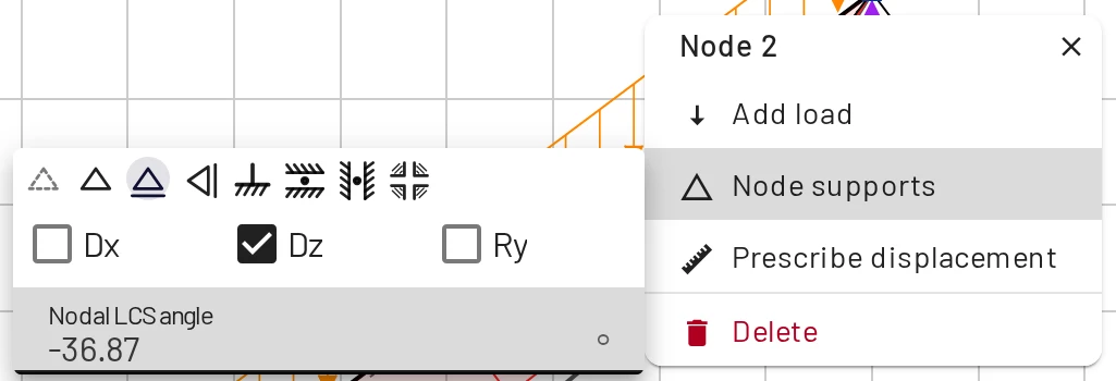
The angle turns the node's own axes. In the default axes, x right and z down, a negative angle turns them counter-clockwise on screen. Inclined supports has more.
The roller now rolls along the slope, so its reaction is perpendicular to the member: kN, from moments about node 1. The pin takes the rest, and with it the whole normal force: −7.2 kN at node 1, zero at node 2.
Make it a vertical roller. Set the angle back to 0 and pick the Vertical roller for node 2. It rolls vertically, so it can only push sideways: moments about node 1, , give 8 kN, and the pin holds the rafter against that thrust. The whole member is in compression.
The three rollers side by side:
| Roller at node 2 | Reaction at node 2 | Reaction at node 1 | from node 1 to 2 |
|---|---|---|---|
| Horizontal | 6 kN ↑ | 6 kN ↑ | −3.6 to +3.6 kN |
| Along the slope | 4.8 kN ⊥ member | 2.88 kN →, 8.16 kN ↑ | −7.2 to 0 kN |
| Vertical | 8 kN ← | 8 kN →, 12 kN ↑ | −13.6 to −6.4 kN |
The bending moment never changes, and neither does the shear force: 6 kNm and ±4.8 kN in all three. Node 1, node 2 and every cut lie on one straight line, the member's axis. The part of the reaction at node 2 that acts along that line has no moment about any of them, so it only adds normal force. The part perpendicular to the member is fixed at 4.8 kN by moments about node 1, whichever way the roller points. The roller's direction decides only where the thrust goes, which matters for the wall or the stair landing that has to take it.
Next steps
Practise: beams with an overhang
Reactions and the largest moment of a beam under a distributed load, with your answers checked at once. Start with O2048; for more, keep only Beam with an overhang selected and press New problem.
Next: three-hinged frame
Four members, an internal hinge and a horizontal thrust: a frame you can still solve by statics alone.